Table of Contents
Atari Asteroids AutoPlay
Introduction
Goal at Beginning of Project
The goal of this project is to use a combination of custom build physical hardware and Microsoft's C# Programming Language to create an automated Asteroids “Player”. Methodologies based around how this will happen are beyond the scope of this description but two components will be necessary. These major parts/questions of the project are: How do I get the Asteroids input into the computer? How do I then interpret the “screen” and send appropriate signals back to the controls?
Goal at End of Project
To be completed at end of project.
Background
This project is something I've dreamed of doing for about 5-6 years. I've seen videos of players playing Asteroids with their extra ship count spanning across their entire screen. I've also been very interested in some day coupling the physical world with my programming skills. I don't know a terrible amount about electronic theory but I have built quite a few electrical projects, never have designed my own circuit. This will definitely be a long and trying process.
Tools Used
We will be using Visual Studio 2010 Ultimate Edition with C# as the programming language of choice. As far as physical tools I have a wide assortment of tools including a an oscilloscope, digital multimeter, etc.
Assumptions
I am using an Atari Asteroids upright cabinet manufactured in 1979. The monitor assembly is an Electrohome G05-801 Black & White Vector Monitor. The installed ROM is Rev 2 which displays “1979 Atari” at the bottom of the title screen.
Electronics Notes
Electrohome Input Pin Assignments (Deflection Amplifier - P703)
| Pin No | Description | Impedance | Voltage |
|---|---|---|---|
| 1 | X | 1K Ohms | +/- 10V (0V Center) |
| 2 | GND | ||
| 3 | Y | 1K Ohms | +/- 7.5V (0V Center) |
| 4 | GND | ||
| 5 | Z | 220 Ohms Min | 0.5V Blanking 1.0V Off 4.0V Full On |
| 6 | Key | ||
| 7 | GND |
Source: Instruction and Service Manual - G05 Monochrome X-Y Monitor "Quadrascan" - Page 8
Programming Notes
None.
Daily Log
3/12/2013 @ 8:35am
Started the write up and research for the project.
3/12/2013 @ 7:18pm
Did some investigation with the oscilloscope. I made this video:
YouTube: Atari Asteroids - Oscilloscope Vector Output
I'm not sure if I'm going to be able to use the vector output as the input into the computer it moves awful fast and I'm not sure serial communications are going to be able to keep up. Another approach I may be able take is to investigate the possibility of watching the input and output to the vector RAM and looking at that for WHERE the objects are. So I'll have to draw them myself.
3/13/2013 @ 1:20pm
So I need to catch up from my experimentation lastnight. I discerned a lot. I made images of all of the Atari schematics:
Atari Asteroids - Drawing Package Supplement (Schematics) - Contains All 4 Sheets, In High Resolution
And then got to work. I looked around and made a few posts:
VAPS - Asteroids Computer Input Project
Reddit - What is the most effective way to monitor the PCB communications of an old arcade game?
A very helpful person on Reddit showed me the world of Logic Analyzers. I found a device online: Saleae Logic. It's an 8 channel USB connected logic analyzer that has software for displaying them all in sequence on the PC. Saleae also has a .NET extensions that allows you to interface with the sensors in .NET. Perfect for what I need it for, so I bought it for $100.
I then got to thinking that now I need to determine where I am going to intercept the data. This is where I found an AMAZINGLY detailed page:
The Secret Life Of Vector Generators, By Jed Margolin
I have also created a local copy (don't kill me Jed!) simply because I know a lot of these times of sites phase in and out of existence. I would hate for all of this great information to disappear. You can find the local copy here. Please always use Jed's site if it is up.
Basically I believe I need to intercept the outputs of XVLD, YVLD, and BVLD. This is where all of the digital signals are condensed into the X, Y, and On/Off digital stream. From here it goes to the DACs which convert it to output to the Electrohome. I hooked an oscilloscope up to one of the leads of one of the LS134(?) chips which I think is XVLD or YVLD. Using the test pattern (which keeps the picture static) I was able to get a good look at the signal going through there. It looks like how I think a digital signal would look on an analog oscillocope… Lines at 0 and Lines at positive whatever voltage with no connections in between. Almost like _-_-_-_-_ or something.
3/16/2013 @ 9:07pm
So I haven't updated this lately mostly because I haven't had a chance to do much. I determined that the best way to move forward was to purchase a logic analyzer from Saleae. They offer an 8-channel 24Mhz logic analyzer that can definitely help with this project.
I'm currently going around and around unable to decide where the best place is to intercept the data. I've found out where I can intercept it but it takes 8+ leads to get anything valuable out of it. XVLD/YVLD turned out to be a dead end as all they do are tell whether or not there is a valid value there. I'm torn in a few different directions…
Get the outputs from DACX1-10* / DACY1-10* / BLVD. The X/Y ends up being 10 bit values which are fed to the actual DACs (B11/D11). I hooked the logic analyzer up to B11 pins 13 thru 6 (DACY10-3*) where Pin 13 (DACY10*) is the most significant bit (512). It can be visualized as follows:
| DACY#* | 10 | 9 | 8 | 7 | 6 | 5 | 4 | 3 | 2 | 1 |
|---|---|---|---|---|---|---|---|---|---|---|
| B11 Pin | 13 | 12 | 11 | 10 | 9 | 8 | 7 | 6 | 5 | 4 |
| Logic Channel | 0 | 1 | 2 | 3 | 4 | 5 | 6 | 7 | ||
| Sample Value | 1 | 0 | 1 | 0 | 1 | 1 | 0 | 1 | 0 | 0 |
| Digit Weight | 512 | 256 | 128 | 64 | 32 | 16 | 8 | 4 | 2 | 1 |
| Value | 512 | 0 | 128 | 0 | 64 | 32 | 0 | 16 | 0 | 0 |
| Total | 692 | |||||||||
Now whats important to note is that the DAC does not have an internal register so it doesn't load it into a register then “pull the trigger” to change the value for the output. As bits come streaming down DACY* they change the voltage. This means the voltage will jump around a little bit (therefore making the beam jump around). Luckily this happens rarely and is accounted for by BVLD… I think.
Anyway, I hooked the logic analyzer up to B11 Pins 13 thru 6, which leaves off pins 5 and 4, which means you lose the last two bits of accuracy. I'm not sure if it is important at this point or not. That means the last two bits are always considered 0. The Saleae Logic software is pretty cool. You end up getting data that looks like this:

Well thats interesting but not really visually useful is it? If you take a vertical slice at any point in that output and assign each channel a 0 or 1 you will get the binary representation just like in the table above. I've compiled the output for each slice (all 336,000 of them) and uploaded them here: 130316_b11_saleae_logic_export.zip
Now that I have 336,000 height values (Y-Axis 0-1023) I was able to compile this chart with gnuplot:
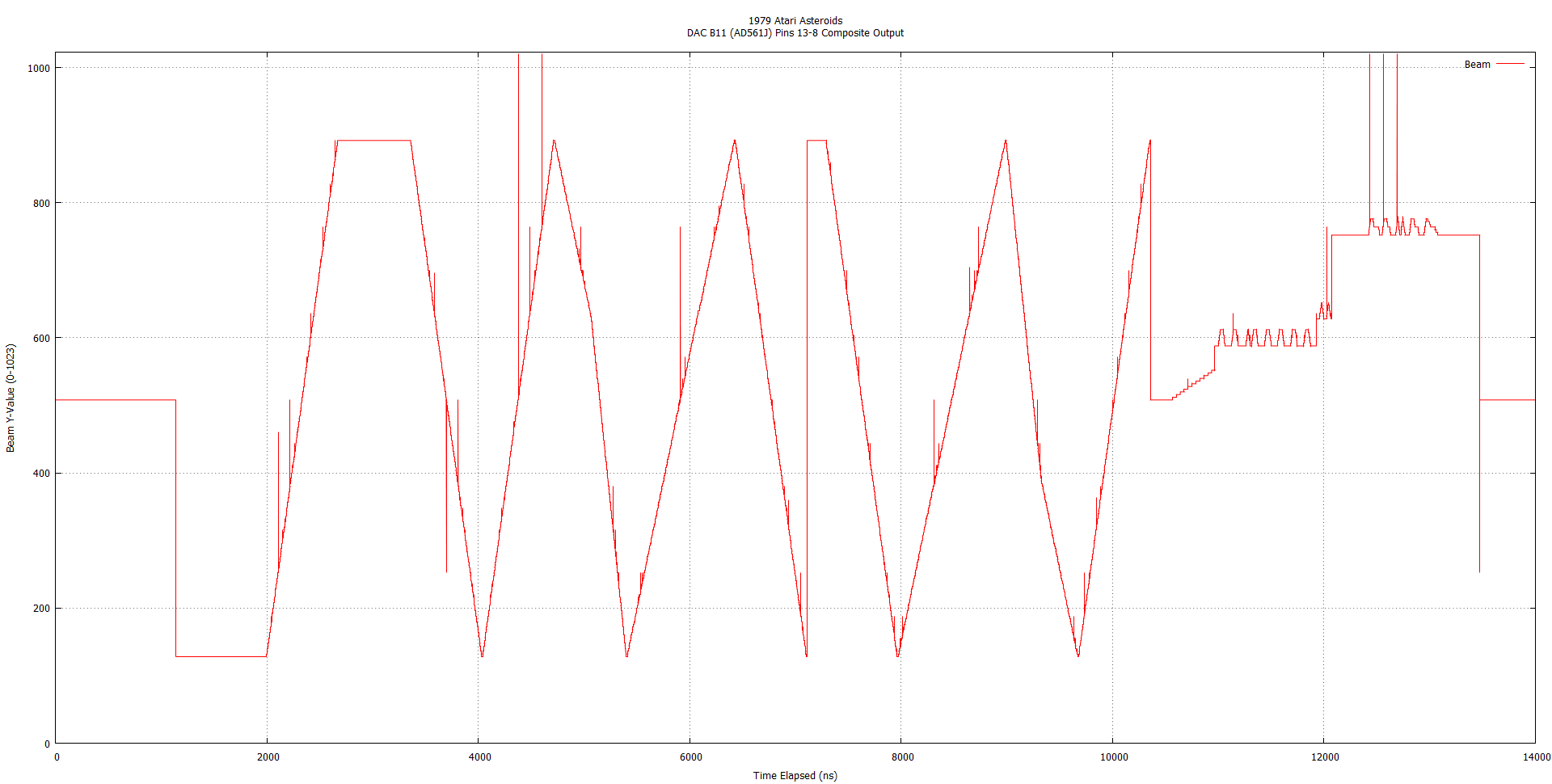
Well HMM that looks a little bit like the horizontal output for the test pattern! Don't quite see it? Heres a labeled version:

Looking at the math here there is an entire screen refresh approximately every 14ms. Do I think I can write code efficient enough to process several thousand points minimum in less than 14ms? I don't really know how long 14ms is in the programming world, but I think even if the application is multithreaded and I have one thread for each interface (1 for each: Beam On/Off, X Position, Y Position, Game Processing) I don't think I can be quite that efficient. I think now would be a good time to give up on the strategy of processing each frame. Even if I process one out of every 10 frames at 140ms (which I think is probably doable) I'm still not sure I can filter through and pick out a frame easily enough. There would have to be some sort of a pattern recognition that would be insanely hard to write and require a lot of processing time. I think my next step is to look at intercepting the commands as they go to the vector RAM.
Now that we're moving in that direction… What do I know? The Vector State Machine seems to be a complicated beast. I believe basically the CPU sends a pulse to the Vector State Machine to turn on. It starts its drawing timers and such and immediately starts reading from the vector RAM. It swaps back and forth between reading and executing until the vector RAM is empty, then it turns itself off and waits for the next command. I'll need to decide on one of two approaches:
- Read from the CPU as it goes into the RAM and just assume that the commands are written to the screen quickly
- Watch that “pulse” line and inspect all of the communications out of the vector RAM and just assume that the vector circuits generate it right away (a given).
Well I'm going to go investigate how to look at the RAM. I don't know how easy this will be without the Asteroids game code….
Major Challenges
Resources Used
Asteroids - The Internation Arcade Museum
Instruction and Service Manual - G05 Monochrome X-Y Monitor "Quadrascan"
The Black & White Vector Monitor FAQ and Guide Version 1.2
Atari Asteroids - Operation, Maintenance, and Service Manual
Atari Asteroids - Digital Vector Generator Schematic
Atari Asteroids - Drawing Package Supplement (Schematics) - Contains All 4 Sheets, In High Resolution
The Secret Life of Vector Generators (Jed's Website) (Local PDF Copy)
Low Cost 10-Bit Monolithic D/A Converter (AD561) DataSheet (B11/D11 Vector DACs)